
Unknown component in-line with ignition power supply
Hi all.
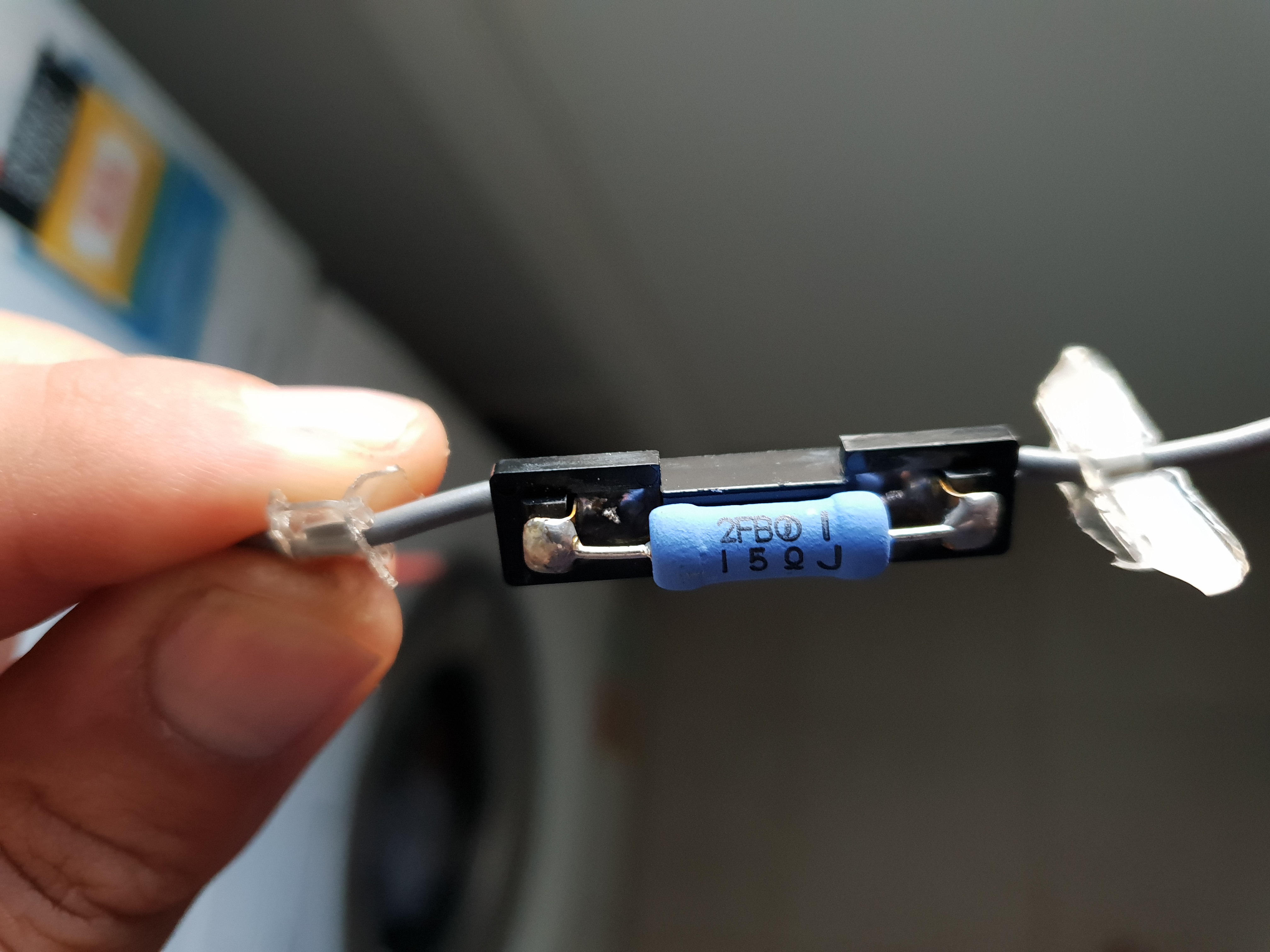
Been rewiring parts of my boat and came across this component which was connected in-line with the ignition power supply from the outboard's wiring harness (2009 Suzuki DF250). This supply had the NMEA2000 network backbone, trim tabs control unit, and a compass lbacklight connected to it.
It was in a sealed plastic sachet. A few checks with the multimeter shows it's not a diode and has a DC resistance of ~15 Ohm. Given I still had no idea what it was, I then decided to cut open the sachet and was greeted with this component which looks like a resistor. A Google search on the printed number on the component has come up with donuts. But that 15 in the part number probably means 15 Ohms.
Everything appeared to be working fine on this power circuit before I went for a re-wire. The resistance seems too high to be an in-line ferrite bead, but what has me stumped is how this resistance hasn't caused a significant volt drop given NMEA2000 backbones are generally rated up to 3 Amps. Even 0.5A load would see a 6V volt-drop.
I'm an EE and I'm stumped.... Any insight would be greatly appreciated.
Cheers.
Tom.


scano
Posts: 1247
Date Joined: 31/05/07
Hmmm
Going to sound odd, it’s not a capacitor is it? (But they normally always have 2x legs)
mid it’s not a resistor or a capacitor, I’d be bloody interested myself. Can’t see a need for anything else in the power circuit
Scotte
Posts: 1147
Date Joined: 07/12/06
That one might be a question
That one might be a question for the guys in the suzuki factory.
chevaps
Posts: 87
Date Joined: 04/01/13
I don't think this is an OEM
I don't think this is an OEM part. Looks like it was tacked on as part of the rigging.
Dale
Posts: 7930
Date Joined: 13/09/05
It’s not a rectifier is it? Outboards power out is usually an A/C current that would need swapping to D/C for the boat power and you use a rectifier for that.
"Just because you are a Character, Doesn't mean you have Character."
Mr Wolf
chevaps
Posts: 87
Date Joined: 04/01/13
The rectifiers are in the
The rectifiers are in the outboard itself. The ignition supply is definitely DC.
Rig
Posts: 2925
Date Joined: 27/12/06
ballast resistor
its definitely a resistor no doubt about that
Sometimes years ago ballast resistors were installed to limit voltage spikes, but not common these days
why is it there? best guess would be the outboard or previous outboard was spiking output voltage or wasn't holding stable on light load and potentially damaging some of that equipment or giving a flicker, hence this solution
you've taken off the heat and moisture insulation so see how you go without it, has this boat had a different motor prior to the Suzuki?
Starbug
Posts: 563
Date Joined: 27/08/09
Yes its a 15ohm resistor.
Yes its a 15ohm resistor. Perhaps used to drop the intensity of the compass backlight
chevaps
Posts: 87
Date Joined: 04/01/13
I think you're on the money
I think you're on the money Starbug
mungus
Posts: 60
Date Joined: 15/03/11
Not sure about Suzukis, but
Not sure about Suzukis, but Etecs have something similar. I'm not going to say this the right way, but their's has something to do with converting the engine trim reading from the analogue signal from the sender to display on a NMEA2000 gauge.
Goin_Fushin.
Posts: 88
Date Joined: 07/12/13
Surge Protection ?
Is the white internals a thermal guard? It could be for surge protection. Sometimes a high load turned on can cause a spike in the circuit. This can be either a sudden increase as the charging circuit tries to compensate for the additional load or a drop in voltage as the load is put onto the circuit.
It can work in two ways. 1. Protecting the down stream electronics from spikes generated from the charging circuit and 2. Protecting the upstream charging system from sudden loads being switched on/off. This can create a dangerous voltage surge into an electronic circuit damaging its critical components especially in voltage sensitive computer electronics used in about everything these days. A resistor when introduced in series with the supply terminals of the circuit helps in checking the sudden rise in voltage and averting a possible harm. These resistors are generally of high amp but low values so that the over all performance of the circuit is not affected.
chevaps
Posts: 87
Date Joined: 04/01/13
After much thought, I think
After much thought, I think Starbug was on the money.
I am now convinced the resistor was indeed used to dim the compass backlight. I should have paid more attention to where the scahet was connected before unplugging it, as this would have almost certainly confirmed the resistor was not in between the ignition output of the wiring harness and all loads (there was no way the loads, particularly the NMEA2000 backbone, would have functioned correctly, as i suggested in my initial post).
I did make an attempt to compare the brightness of the light with and without the resistor in series, but unfortunately the globe's element was broken, so that was a fail. But i'm still convinced none the less.
Thanks to all for taking the time to provide your thoughts.
Starbug
Posts: 563
Date Joined: 27/08/09
Any time
Any time