Rewiring the Boat
I am hoping anyone can chime in and let me know if I am doing anything wrong or if there's a better way to do it.
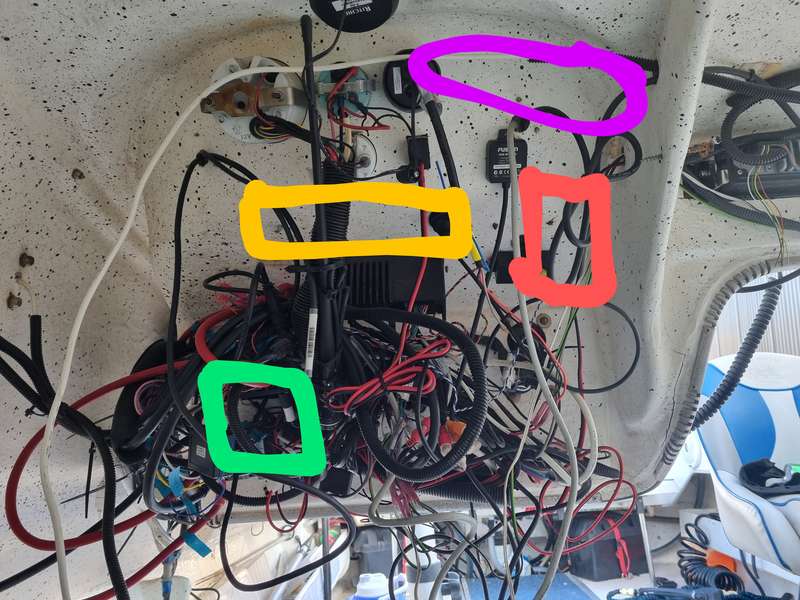
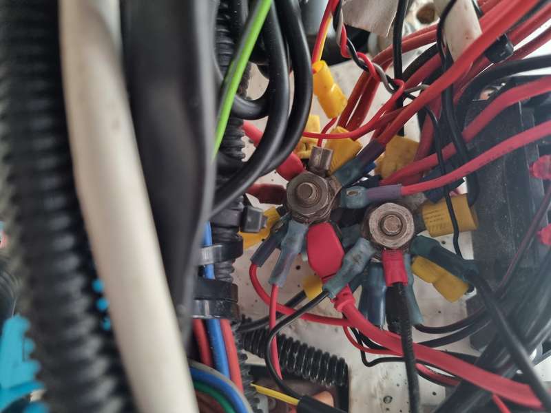
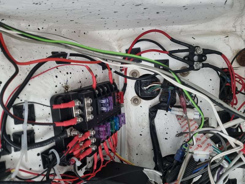
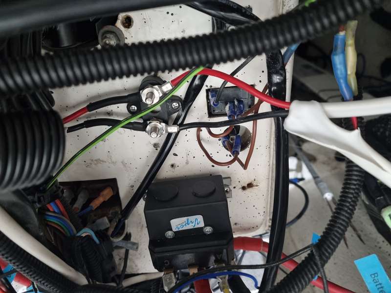
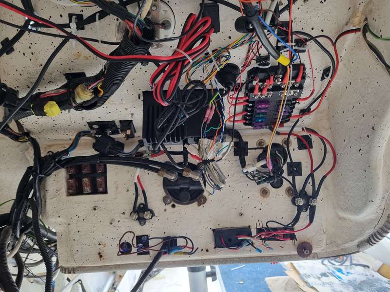
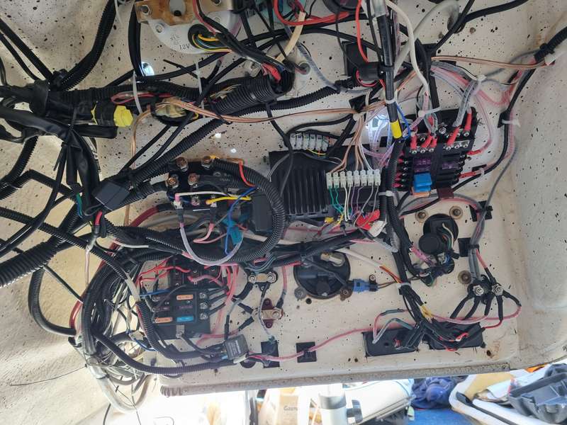
I have started trying to neaten up the wiring behind the helm as it came to me in a complete bird's nest and I have just added to the mess over the years. All of the below are connected on a single mini bus bar with the negative and positive cables all overlapping each other to fit on it near the green square in the pic below. Also the power wires from the dual battery switch to the mini bus bar that powers everything are only thin gauge wire.
- I have a 6 gang switch panel where the green square is and off that I run: anchor light, stern lights, livewell pump, lightbar on bow and nav lights. The share a common negative wire that runs back to the stern.
- I have two bilge pumps on independant switches with 3 core wire running back to the stern.
- Ctek panel mount for charging or output for connecting air pump to.
- A deckwash on an independant switch with 2 core wire running back to the stern.
- NMEA backbone connected to my HDS7 and also to the DF90.
- Icom VHF radio
- 2x speakers each side connected to a Fusion Stereo as well as the Fusion bluetooth dongle.,
- Markfish, HDS7 and Furuno 627 linked all linked up running a transducer for both.
- Drum winch connected directly to second battery with switch and circuit breaker. All connected by Bell Viper wiring kit.
- Then I have the outboard wiring loom which is connected to a Fell Marine MOB+ wireless killswitch.
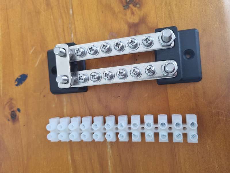
To get the ball rolling I am going to start chipping away at the devices at the helm i.e. the devices that don't run wiring back to the stern and connect them to a new bus bar where the red square is that runs off the primary bus bar and off that I plan to connect. I am going to mount these all nice and neat and where possible give each one its own spot on the bus bar.
- NMEA backbone
- Sounders and Markfish
- Deckwash
- Fusion Stereo
- Ctek panel
I also have a mini bus bar that I will install next to this for the low voltage wiring being the NMEA wires connecting the Markfish/Furuno/HDS and the Icom that share GPS and the speaker cables. Once installed I'll waterproof each connector with some putty etc.
I"ll also mount the NMEA backbone an T pieces where the yellow rectangle is and coil the transducer cables up away from the bird's nest.
My next plan of attack will be to replace the wire between the battery switch and the helm with heavier gauge wire (10 AWG?) and replace the single mini bus bar with 2x mini bus bars (pos and neg) and off this I will run all of my primary devices being the outboard wiring loom and Fell Marine MOB+, VHF radio, drum winch switch, switch panel and bilge pumps and well as to the positive and negative of the new bus bar running all of my other devices.
Once all of this is done I'll be looking to replace the switch panel with one that is illuminated/have LED lights for each switch as well as fuses/circuit breakers for each switch.
Officially off the Pies bandwagon



dmck
Posts: 487
Date Joined: 07/03/19
where are ......
the fuses??
I'll add a lot more comments tomorrow.... too many commitments today...
but...
start adding up the current draw to determine likely maximum draw.. eg lights + radios+ bilge pumps +FF + GPS + + + + .....
this will determine the size of the cables from the battery(s) to the dash board....
Jackfrost80
Posts: 8157
Date Joined: 07/05/12
Cheers mate. Most components
Cheers mate. Most components have an inline fuse or a fuse in the switch in the case of the bilge pumps and deckwash.
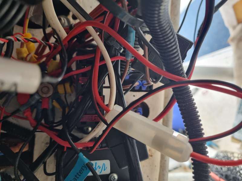
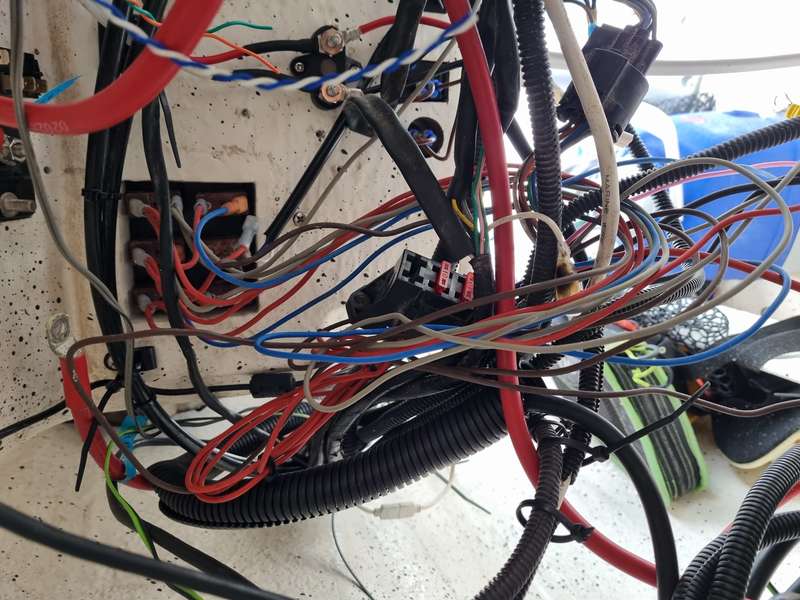
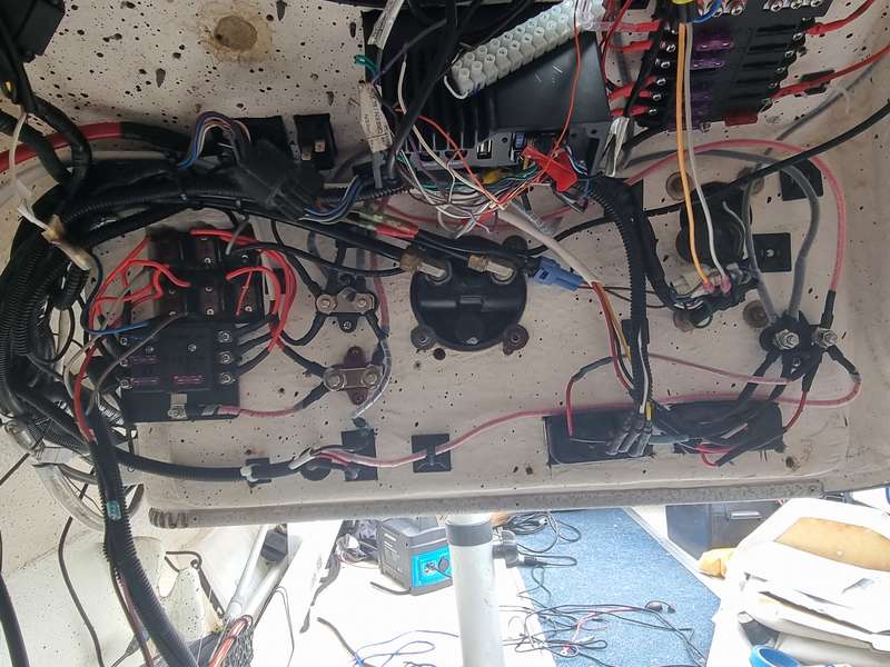
Check the bottom pic. Will be a fecking nightmare if I ever have to troubleshoot on the water which is my main reason for wanting to clean it all up.
Officially off the Pies bandwagon
Jim
Posts: 1352
Date Joined: 05/05/06
I wired mine all up to a
I wired mine all up to a fuse box that has a mains positive and negative coming from the battery. At least all your fuse are together in one spot and if the fuse blows a red light comes up on that fuse. I'm happy with it so far. Ive done what you are doing as the wiring was all over the place. It's bit of an art getting it to look like a professional job. Mine only came out slightly improved but at least I know how it all works.
Bend over
scano
Posts: 1247
Date Joined: 31/05/07
Agreed
As stated above, get yourself a centralised fuse junction box. (The narva ones from places like repco etc are good). Then you just have to run a descent size positive and negative cable from battery to under the dash. Also, that gives you the ability to cut out all the inline fuses. Makes the wiring far neater and simple
piscetor
Posts: 254
Date Joined: 13/05/16
rewiring boat
Do your slf a favour. get rid of the fuses and go tocurcuit breakers saves a lot of grief in the long run. No need to change fuses you just reset the switch.
Filletmaster
Silver Fox
Posts: 1120
Date Joined: 19/06/14
Good luck to you Frosty.
That second picture isn't one of your mind after a night a big NYE at Belmont park by any chance?.
My wife understands why I clean my rods n reels in the shower....
Jackfrost80
Posts: 8157
Date Joined: 07/05/12
I don't do Science Fiction
I don't do Science Fiction
Officially off the Pies bandwagon
Rob H
Posts: 5893
Date Joined: 18/01/12
Haha that looks exactly like
Haha that looks exactly like my old Cruisecraft before I rewired it.
Somewhere on here is a thread, but I can't find it.
As others have said;
And maybe use a piece of Starboard or similar to mount it all on behind the dash?
Give a man a mask, and he'll show you his true face...
The older you get the more you realize that no one has a f++king clue what they're doing.
Everyone's just winging it.
mikeurnot
Posts: 97
Date Joined: 05/05/11
rewiring the boat
I did my barron sportsman boat a few years back . Ripped out every bit of wire . Got a new bus board also a new cental panel for all my lights etc all in one place on console . New wires all through out and fuses . Dual batteris wirering was also done .
Took about a week of off and on to finish . No more bird nest . Looks great and neat. Also another point is when you do it yourself you will know if trouble happens down the track it is easier to find .
Have fun .
scubafish
Posts: 964
Date Joined: 15/08/12
Look before you leap
https://www.youtube.com/watch?v=tdur_Ln-9cE&ab_channel=PacificYachtSystems
https://www.pysystems.ca/resources/diagrams/
https://www.ebay.com.au/itm/175108052789?hash=item28c540d735:g:AaoAAOSwoeJhb4Cz
https://www.ebay.com.au/itm/265574654089?hash=item3dd57ba089:g:lYwAAOSwrFxg0~7r&amdata=enc%3AAQAHAAAAwJqouZ%2BoXsdAXX%2FBt116Jh6k57MJyByWf2MrsY4wAwXlYHb0JcRpjr9r1QNQvKY2EU80S4AdNSCNCmry%2BRwl%2FuHmULZALf5pgsgg7RtK8wqHaxuslDhBS2Btza2Mealp6Biy8L0Sx1y62ssFTSvCd1kb5kroPDWcopon%2BF7Pjw3R7PsDAQhxQIMQNfN0iRrxs9Yjlnl3mmMWC6p9tK7Hggdz%2FlPw8ql0bfOcv1nDc39TBxMrG02HiLeQDJG%2BVD0Lbg%3D%3D%7Ctkp%3ABk9SR_DGmvbhYA
Can connect switch panel to fuse panel.
Gerhard Jacobs
Posts: 15
Date Joined: 04/11/19
Fuse box with neg bus bar
I have recently done mine as well and have used something similar to https://www.jaycar.com.au/12-way-fuse-block-with-bus-bar/p/SZ2032
This has worked very well. Easiest way is to run a negative and pos wire from your house battery to the fuse box and then have all appliances going to the centralised fuse block. Make sure you know the current draw as these are only rated to 100A combined draw and 30A on a single port. The fuse box has a light that warns you if a fuse has gone. Super easy to mount and keeps everything neat and together. Place a circuit braker on the main wire connected from the house / main battery to protect that wire, no wire should be run without a fuse or breaker in it.
Make sure you use tinned marine wire and not the standard auto copper wires. Something nice and thick from the back to the front 6 b & s (depending on combined draw, they are rated so easy to check, always go slightly higher than what you need) or similar to prevent voltage drop.
Happy to help you draw up some plans and sketches to make the explanation clear. I have attached some rough sketches for you. The Neg Buss can be on the fuse block. This includes a switchboard with everything individually fused. The VSR can be replaced with an isolation switch or a circuit breaker if you want to break it manually every time.
Cheers
Jackfrost80
Posts: 8157
Date Joined: 07/05/12
Cheers for the advice and
Cheers for the advice and write up and that was the exact fuse block I bought. Can't beat good old Jaycar!
I made a fair bit of headway today picking off the easy components like the VHF, sounders, Markfish and stereo and am already accumlating a large amount of leftover cable.
Once I get to the switch panel I might hit you up for some advise if I get stuck but I am looking at a switch panel with built in circuit breakers.
Officially off the Pies bandwagon
Gerhard Jacobs
Posts: 15
Date Joined: 04/11/19
No problem
Feel free to make contact if you get stuck. I have only heard good things about those switchboards with the circuit breakers in them. Although for me that would void the need for additional fuse block as its essentially doing the same thing. Unless you cluster the switches and have a few things running of one switch. Guess a double backup is also not the worst thing that you can do with electronics.
Gerhard Jacobs
Posts: 15
Date Joined: 04/11/19
(No subject)
Cannot figure out how to add an image to the post?
Rob H
Posts: 5893
Date Joined: 18/01/12
The quintessential
The quintessential Fishwrecked problem.
Easiest to just put it in a new thread
Give a man a mask, and he'll show you his true face...
The older you get the more you realize that no one has a f++king clue what they're doing.
Everyone's just winging it.
lastcast
Posts: 221
Date Joined: 04/04/13
Ditto have never been able
Ditto have never been able to add an image.
Any help on that would be appreciated.
lastcast
Posts: 221
Date Joined: 04/04/13
Ditto have never been able
Ditto have never been able to add an image.
Any help on that would be appreciated.
sea-kem
Posts: 15207
Date Joined: 30/11/09
Love the West!
sea-kem
Posts: 15207
Date Joined: 30/11/09
Love the West!
sea-kem
Posts: 15207
Date Joined: 30/11/09
You need to use a third
You need to use a third party site, I use imgur. Select BBcode it will automatically copy the image and just paste here.
Love the West!
davewillo
Posts: 2667
Date Joined: 08/09/16
I'll try that Andy as I
I'll try that Andy as I haven't worked it out to date!
PGFC member and lure tragic
Marineboy
Posts: 845
Date Joined: 14/03/14
Dolly
That's a cracker dolly from the Hillary's fuel jetty !
My spots are so secret even the fish don't know about them !
davewillo
Posts: 2667
Date Joined: 08/09/16
Yeah not bad hey? Was
Yeah not bad hey? Was actually a bit further. Not sure why my mate looks so serious though!
PGFC member and lure tragic
Mark_M
Posts: 212
Date Joined: 10/04/15
imgur
Is that a free service sea-kem?
sea-kem
Posts: 15207
Date Joined: 30/11/09
Yeah it is mate, a really
Yeah it is mate, a really good site. I gave photobucket the flick when they tried to railroad users into paying for their site.
Love the West!
davewillo
Posts: 2667
Date Joined: 08/09/16
It must be easy if I got it
It must be easy if I got it to work Andy!
Even if mine is just one fish and not a freezer full!
PGFC member and lure tragic
sea-kem
Posts: 15207
Date Joined: 30/11/09
Ha ha It's a sexy lump Dave
Ha ha It's a sexy lump Dave ;P
Love the West!
Jackfrost80
Posts: 8157
Date Joined: 07/05/12
A few pics added. I've spend
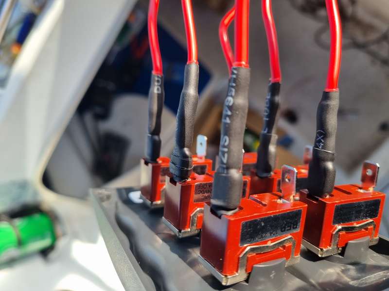
A few pics added. I've spend countless hours in the cuddy now cutting, crimping, heatshrinking, runs back to Jaycar. Testing voltage, amps. It's definitely a labour of love. All terminals used are heat shrink glue with heat shrink on top or for the larger ones I've used a double layer of glue filled heat shrink (4mm for cable up to terminal and 6mm over the sleeve of the terminal.
I've added a few pics but have decided to run a 40a from the battery switch to a mini bus bar at the helm. This will feed the circuit breakered switch panel (light bar, live well pump, nav lights, anchor lights, deck lights) and ignition. This will connect via 40a cable to a mini bus bar that will feed bilge pump 1, bilge pump 2 and deckwash all on standalone fused switches. This will connect via 40a cable to the fuse block for everything else. I once everything is hooked up and tested I'll pop flexi conduit around the cable and zip them all in nice and secure.
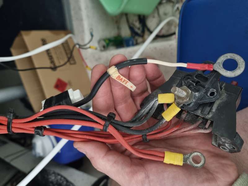
I still haven't touched the wiring loom or the cables for the switch panel and the anchor winch wiring needs a bit of work but checkout the size of the white battery cable that was feeding everything! Those red wires connect the switch panel to a fuse block with metres of unessesary cable rolled up which I can completely do away with once I find a switch panel with independant circuit breakers.
Officially off the Pies bandwagon
Jackfrost80
Posts: 8157
Date Joined: 07/05/12
Back into it this morning and
Back into it this morning and making some serious headway now.
All the wiring in pic 8 is for the switch panel and it all goes back to the bow and each switch has an individual positive going to a fuse block. They've bypassed the switch panel with the wiring going to the bow, looped the unnecessary wiring 3x around and back to the switch panel. Once I replace the switch panel I can remove about 6m of wiring back to the bow, the fuse block and all those individual positive wires from the switch.
Officially off the Pies bandwagon
Jackfrost80
Posts: 8157
Date Joined: 07/05/12
Last bit of work before a few
Last bit of work before a few days camping.
Officially off the Pies bandwagon
Jackfrost80
Posts: 8157
Date Joined: 07/05/12
New switch panel wired up for
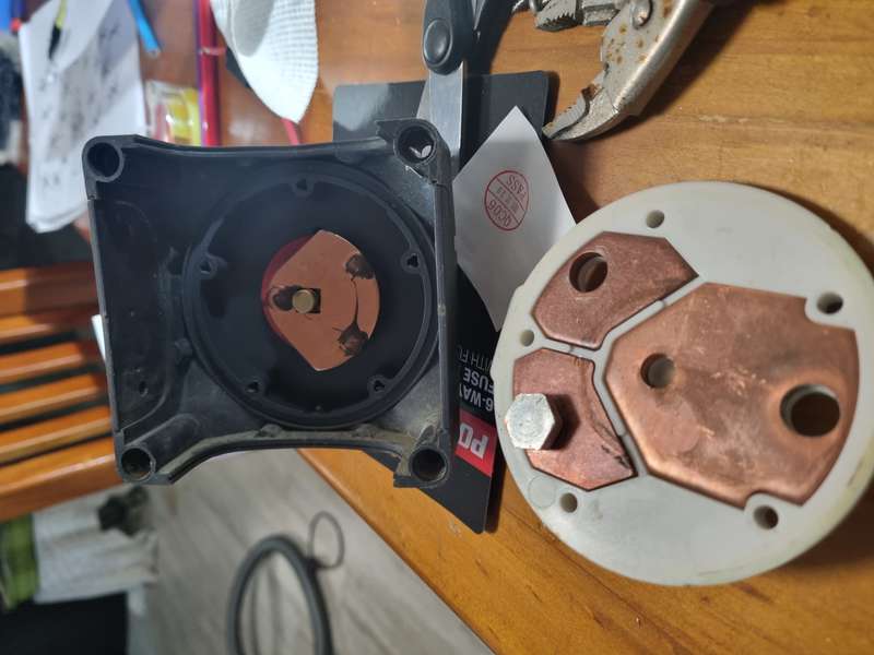
New switch panel wired up for connection, main switch pulled apart and checked and all wiring has been run to the stern. I've decided to also run wiring to connect my Ctek panel connector direct to the battery so I can charge it without switching on everything else in the helm.
Officially off the Pies bandwagon
Jackfrost80
Posts: 8157
Date Joined: 07/05/12
Just finished the 12v wiring
Just finished the 12v wiring except the light bar and am moving onto running the NMEA and speaker wires into a mini bus bar and then onto wiring the switch and VSR and connecting the batteries.
Still got a lot of conduit to place on and then securing/ziptying all the wires.
Officially off the Pies bandwagon
Jackfrost80
Posts: 8157
Date Joined: 07/05/12
Finally finished! This is a
Finally finished! This is a flat out time of year for me working most weekends. Ended up having to replace my dead front two speakers so while I was patching up screw holes had a few other areas to patch and little jobs whilst the batteries were out. Finally replaced the hinges with butterfly clips on my anchor well hatch to gain access to the winch and installed sealing tape around recess, replaced my deck filler and fuel hose, removed the fuel flow sensor and installed new fuel line, Loctite on all those fittings bolts that rattle loose over time.
It's not as neat as I imagined especially after reinstalling the anchor solonoid but I know where everything is and everything is now fused, I can run my auto bilge pumps independant of the main switch, finally have an Anderson/cigarette 12V output/charging input and whatever was causing the phantom amp draw is now gone.
Officially off the Pies bandwagon
dmck
Posts: 487
Date Joined: 07/03/19
The most important thing is......
You know how and where it is wired... and now have confidence that it is safe and meets your needs.
A job well done... now stop worrying and start fishing!